LCMR200 Lineár Konvejor Modul
Fejlett lineár konvejor modul nagy sebességű szállítási feladatokhoz.
Rövid és nagy sebességű szállításra is képes
Egyedi ID (azonosító) felismerés
Abszolút pozícionálás
Beépített driver és minimális vezetékelés
Jellemzők
A már megszokott "passzív pálya” helyett “aktív szállítás”.
A szállítás aktív gyártási folyamattá konvertálása jelentősen megnöveli a hozamot.
01 Ütemidő csökkentése
Nagy sebességű, precíz pozícionálással rendelkező szállítással és a kocsikon történő szerelés lehetőségével az ütemidő akár a felére is csökkenthető.

02 Rugalmas gyártósor
Az LCMR200 moduláris kialakításának köszönhetően gyártósorának méretét a szükségleteknek megfelelően növelheti vagy csökkentheti, későbbi átalakításokat is könnyedén hajthat végre. A kocsik egymástól függetlenül programozhatók, ami további szabadságot jelent a folyamatok tervezésében.
03 Egyszerű karbantartás
A zárt felépítésű egységek alacsony részecske-kibocsátással és standardizált alkatrészekkel maximalizálják az élettartamot, megkönnyítik a karbantartást és a minimumon tartják az esetleges gyártósori leállást.
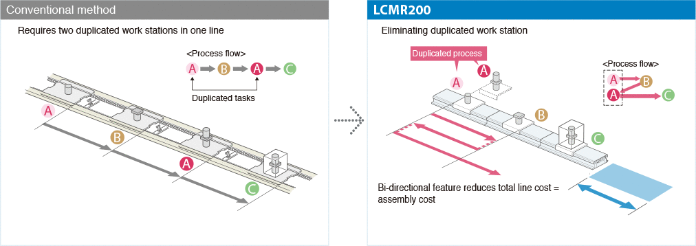
04 Helytakarékosság; folyamatmegosztás lehetősége
Kétirányú szállítással és a kocsik egymástól független mozgatásával a gyártósor térigénye és üzembe helyezési költsége is csökkenthető.

Példa horizontális körforgásos kialakításra

Egyéb adatok
| Drive method | Linear motor with moving magnet type core | |
|---|---|---|
| Position Search | Magnetic absolute position sensor | |
| Maximum payload | 15kg | |
| Maximum speed | 2,500mm/sec *1 | |
| Repeatability | +/-5 μm | |
| Mechanical tolerance between robot sliders | +/-30 μm (Dowel hole standard) | |
| Total stroke limit | 25.5m *2 | |
| Maximum number of robot sliders | 64 units *2 | |
| Minimum spacing between robot sliders | 210mm *3 | |
| Main frame dimensions | Max. external size of frame cross-section | W175 × H109 mm (Including robot slider) |
| Linear module length | 200 mm / 300 mm / 500 mm / 1000 mm | |
| Robot slider length | 198mm | |
| Weight | Linear module | Approx 20 kg [Per 1 m of linear module] |
| Robot slider | 2.4kg | |
| Power supply | Control power supply | 48 VDC +5 %, -10 %, Max. 30 A *4 |
| Motor power supply | 48 VDC +/-10 %, Max. 30 A *5 | |
| Operating environment | Operating temperature | 0 ℃ to 40 ℃*6 |
| Storage temperature | -10 ℃ to 65 ℃ | |
| Operating humidity | 35 % to 85 %RH [No condensation] | |
| Controller | YHX controller *7 | |
*1. When the conveying weight exceeds 10 kg, it will drop to 2,000 mm/sec according to the weight.
*2. It may differ depending on the system configuration.
*3. When the jig palette to equip to the robot slider is longer, it shall be the jig palette length + 10 mm.
*4. Up to 10 m linear module can be supplied with the optional 1000 W power source.
*5. Up to 2 robot sliders can be supplied with the optional 1000 W power source.
*6. Operate LCMR200 in the temperature environment (+/-5 °C) that installation and adjustment were performed.
*7. The YHX controller requires a separate electrical power supply.
Standard profile specification
| Applicable controller | YHX-HCU | |
|---|---|---|
| Operation method | Point trace point No. specified positioning and direct value coordinate specified positioning. | |
| Comparative robot | LCMR200, LCM-X and GX series (LCMR200 and LCM-X cannot be controlled together). |
|
| Interface | YHX-PP, and field network communication | |
| Operation type | Absolute position moving | |
| Maximum number of points that can be registered. | 65535 | |
| No. of control axes (Total of sliders and single-axis robots, however, up to 16 axes for single-axis robot) |
EtherCAT | 64 |
| EtherNet/IP™ | 64 | |
| PROFINET | 64 | |
| CC-Link | 22 | |
| Main input and output See the manual for other functions. |
All axes target input | Servo ON/OFF switch/Interlock/Alarm reset |
| All axes target output | Servo State/Interlock State/Alarm State/Heart beat/Emergency stop State | |
| Individual axis target input | Servo ON/OFF switch/Return to Origin/Positioning moving inside the control range (including LCM relay operation)/Slider insertion preparation from outside the control range/Slider discharge to outside the control range/Jog movement, inching movement/Movement Stop | |
| Individual axis target output | Servo State/Return to origin State/Output specified point No. for various execution state display/Current position/Axis alarm State | |
| Main remote command See the manual for other remote commands. |
Writing/reading of setting data | |
| Alarm check | ||
| Writing and reading of integrated running distance and No of transits. | ||
